


This will be a fully scenicked and operations-wise equipped dcc-ex layout, that is meant to test run some aspects at a smaller scale before sinking a lot of money into a larger project.
The Layout will measure only 160cmm by 28 cm (roughly 63in by 11in). It will have one servo driven turnout, one servo driven derail, two 15,6MHz RFID readers, four IR track occupancy detectors and two or three signals, as well as WiFi and lighting.


In addition to that, it will feature 3D printed trees, details and scenic elements. I will ballast and weather the track and dress it up with static grass.

Expansion Modules
To test module connections and seams, that I will have with the lift out sections planned for the pike, I decided to add two small modules to each side of the Test Layout. This way I can experiment with trackwork alignment and electrical connections across layout seams. It also helps experimennting with scenic construction and hiding these seams. Adding a few feet of track also improves „operation“.
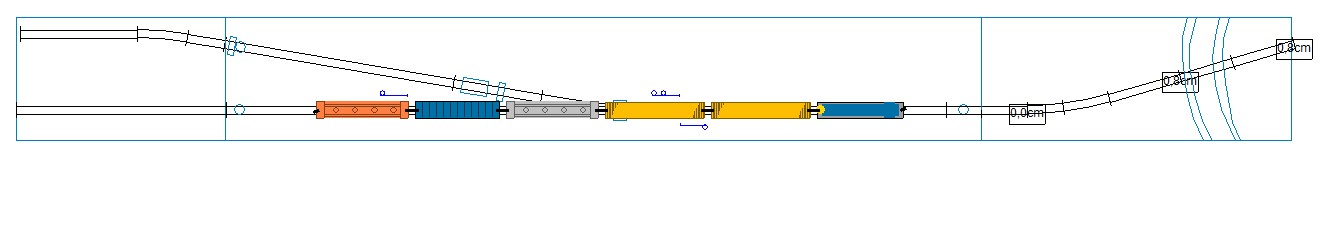
Tha basic design of course hasn’t changed, I only added a 60cm radius curve to the main line on one end and to the siding on the other. The siding will now fit a small industry and thus offer two spots.
There is now enough track to clear the turnout with a 5 car train (plus loco).
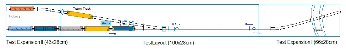
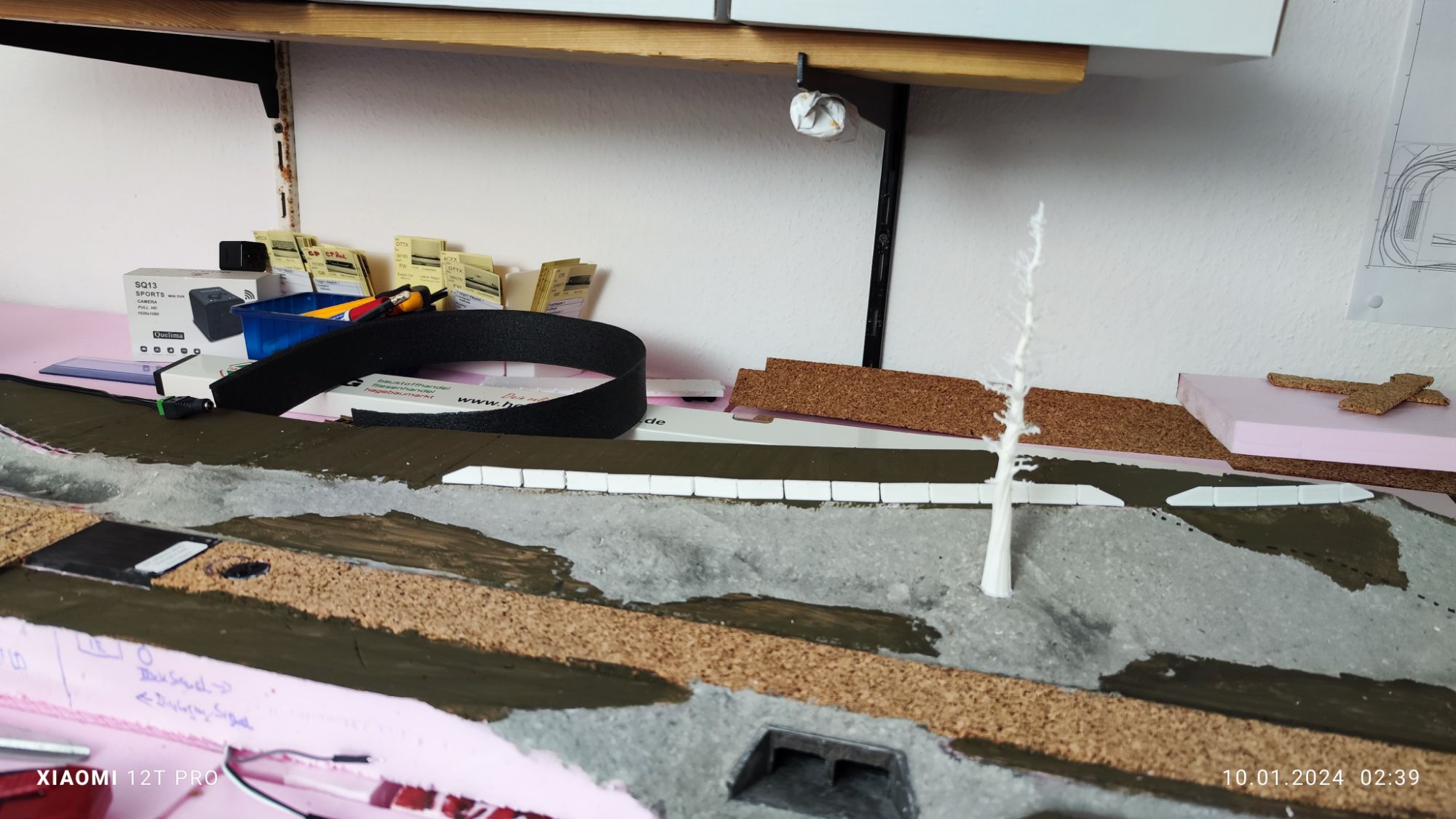
As this is only a test layout (that I am ready to scrap after it served its purpose, I’m using styrofoam as its base (which is not very stable) and used scrap pieces of styrofoam board lying around in the workshop, which I glued together using construction adhesive, forming a somewhat uniformly shaped base.
If I decide to keep the finished layout, I can always add a wooden frame underneath at a later time. In the meantime it sits on top of the baseboard of my large layout (which has no track yet, as I still have to glue down the styrofoam baseboard).


As the sculptamold takes several days to thoroughly dry, I have some time to work on the electronics. The DCC-EX Command Station is build on an Arduino Mega WiFi Combo, which connects to a dedicated router for my pike. Both RFID readers will be grouped (concentrated) to an ESP32-WROOM-32 Module, as I use RS522 readers, which are not 5V tolerant. The ESP board runs on 3.3V, so that’s perfect. It is also capable of handling all the IR sensors and likely all the signals too, while providing a webpage with added functionality (like custom created RFID switch lists or train manifests in the far future). I might switch to a less powerful ESP MCU or at least to an even smaller form factor for the simple tasks at hand though. Scroll further down for more on this.
well the signals are another story. The first plan only had three, but now I’m up to seven, as I want to experiment with block occupation and signaling, by defining three mainline blocks on the test layout, each protected by one signal in each direction. One block will have the spur and thus a diverging signal, as well as a dwarf signal to protect the spur exit.
Originally I wanted DCC compatible signals using ATtiny85 MCUs of which I have a bunch at hand. And this might be a great chance to experiment with these too. However it’s very likely, that these will receive a special electrical 3D printed socket, that would allow me to take them off the layout for other uses or maintenance.
Next Steps
The servo based turnout machine, the derail and the two RFID readers are currently preventing me from glueing the tracks. These are the obvious next steps.
Turnout Machine

These (or this, in case of a manual derail) will be controlled by an Arduino Nano or directly by the DCC-EX Command Station. Likely the nano, becaus I like the modularity of things. A nano is cheap, adds only about 4-5 Euros to the price tag of two turnout motors (one Tortoise for comparison costs just short of 27 Euros here at RD-Modellbahn). I will likely spend less than half for two including MCU.
To Do…
Derail
In order to have a functioning derail on the main layout, I plan to test different designs on this test layout. On design – manually operated – seems to be a great candidate. I’ve been following „Boomer Dioramas“ on YouTube (Check it out, I mean it. Solid great stuff!) for quite a while and his modeling video are a great source of inspiration. So I will give his design a try. Here is the video featuring the derail: „Modeling A Realistic „Derail“ Device (Part 1) | River Road – Vlog #57″ (it is a mini-series and definitely worthwhile to watch).
My design: Still to do…
RFID Readers on ESP32 Concentrator

I designed 3D printed roadbed-bases for the readers at the same height my cork roadbed has. A channel needs to be cut into the styrofoam for the base. After fitting int at the exact heigt, it can be glued into the carving with construction adhesive or chaulk, or what ever the styrofoam tolerates while bonding well to the PLA plastic.


To Do…
Thoughts on operations
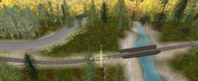
The test layout can be considered part of the pike. It might be a fictional spur at Hyder, AK just around the corner from the Stewart Bulk Terminal, or some location on the Nass River Subdivision or the Alice Arm Branch. But wherever it could be located, it is one branchline with a trailing spur near the end of the line. Beyond the bridge, the track had been removed and the right of way abandoned years ago. The track ends in a pile of gravel with a derail and a few warning signs right after the small bridge.

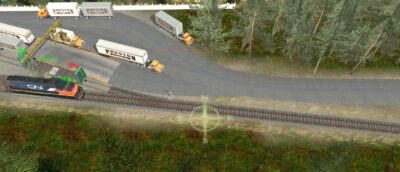
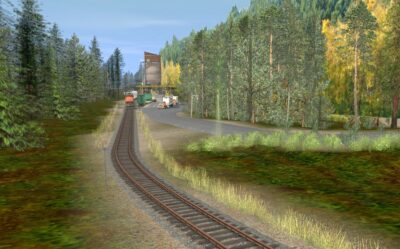
The single industry here is a truck to rail transloading facility. Possibly a team track, perhaps a trucking business adjacent to a bulk transloading facility. Obviously most of the industries area is not modelled at all. I will likely add signs indicating that trucks are to use the road leading into the backdrop to unload or think of something clever, if this layout becomes permanent. The following images show a possible facility as modeled in Trainz. Rail-Sim.


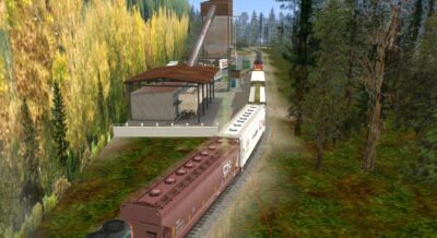
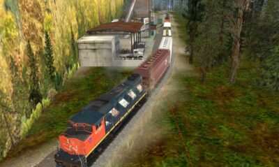
With this industry near the end of the line and the spur facing against the ariving train (trailing point), means locomotives have to go there engine first to be able to switch the trailing spur. As cabooses have become obsolete on modern railroads, and way cars are a bit unusual for the BC Northern, the small train serving this spur utilizes a distributed power unit (DPU) in the form of a backwards facing locomotive at the rear of the train. The engineer switches engines prior to the return trip for a safe and smooth ride home. Any cars picked up on the trip here might also be part of the arriving train, as are some for the return trip, destined for the forward facing (then trailing again) Spurs along the line.
Incorporating a few steep in-/declines between the modeled area and wherever it will connect to the main layout might even justify the second prime mover on such short trains.