After years of armchair railroading, I wanted to build something in 2023. That was in spring, I guess. Now winter is coming and I built not much. Got me another 3D printer, however. So excuses are getting lame and lamer by the minute. It’s time. To. Build. Something.
My plan is to get on with the plan mentioned here and for the final concept, I need a Rail Barge interchange. I could have been done with just a slab of styrofoam, sanded and painted, but I actually wanted more. Here, I wrote about Alaska Marine Lines (AML) and their 400+ foot Rail Barges. A concept I really like, especially as they also carry containers, break bulk, vehicle, housing, wind turbines, you name it. But with eight tracks and just short of 400ft track length, the prototype is much too large for my layout. I need a smaller variant. And this is the post to present this new Rail Barge.
The barge will be built using 3D printed parts as well as traditional model building resources like wood, styrofoam, styrene, etc.
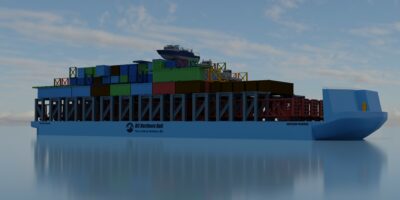
The 5 track barge will feature about 97,5cm (approximately 85 m or about 278 ft) of track each and thus each track offers enough space for three passenger cars or TOFC flat cars, auto rack cars or centerbeam flat cars, as well as space for about four modern box cars, covered hoppers, woodchip cars or tank cars.
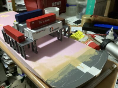
As can be seen on the image above, containers will be carried above the tracks. The main load will be carried at a 90 degree angle to the longitudinal axis and the tracks, where containers and flat-racks from 40 to 56 ft can be transported. Shorter containers can be carried on top of a container palette, which is used for dimensional loads as well as for combining two 20 or 28 foot containers back to back. Stackable flat racks are used for the same purpose, as well as for transporting construction supplies or machinery.
The gallery below show various photos from the build process.


The trackplan exists in several iterations, of which the first one was made with XtrkCad and later recreated in Trainz Railroad Simulator (T:ANE). This again was captured as an aerial screenshot and drawn over on my iPad. So there is quite a lot of leeway regarding radius and track geometry in the drawings below.
I want to achieve a trackplan that offers interesting operations, is suitable for 1-3 crews and designed in a way that allows for uninterrupted work on the industrial trackage or on the classification yard trackage. The latter is combined with the barge loading, but that can easily be designed with a similar interruption free operation in mind.
If this wouldn’t completely congest the aisles, it would even allow for more crews, but that’s another story.
There are some principles I want to follow during the build. I decided to handlay most of my turnouts, as that would give me maximum flexibility with the track geometry. It will also allow for the elimination of S-curves. At least in such a way, that my Athearn 85ft TOFC and passenger cars can safely navigate such sections. I want to have easements and superelevation on the mainline.
I will have to include enough trackage for the barge and classification yard, but not necessarily six tracks as shown in the image below. The plan above has a simpler trackplan, but sacrifices the interruption free barge operation.

The first obstacles have arised. I found the need to include a lift-out dection to be able to access the far lower left corner of the plan below. This is not desirable, but other than eliminating any track beyond arms reach, there is no other option at this time.

Now for the port, I will have to include a two-track railway slip bridge and a vehicle ramp for side access to the barge. A slip ramp into the water would be a nice add-on to allow for specialized vessels to serve the communities along the coast of the Portland Canal and branching inlets.
This way a ship like on the following photo could form an interesting addition to the layout (especially when thinking about the possibility of micro R/C modeling.

These vessels load and unload on boat slipways, like shown on the following photo.


