


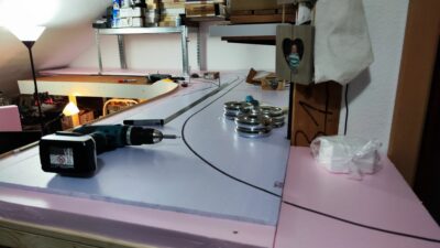
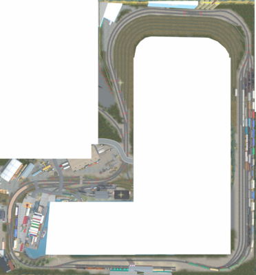
So, after year’s (decades actually) of armchair model railroading, I’ve finally started to build the pike. The title image shows the latest train sim iteration of the layout planning stage. But I’ve actually started with the benchwork.
And what a chaotic ride this already was! I’ve run into problems at every aspect of this endeavour. But I’m already rambling without having even started this article, of which there has been a previous one, which I scrapped just a minute ago. So with that being said, welcome to the ride. I’ll try to structure this a bit.
Layout Plan, Restrictions and Requirements
As usual I made a digital „train sim“ plan and an XtrkCad plan. The first allows me to play while building the pike and actually test drive the operational aspects of the layout. It’s also great for some casual switching.
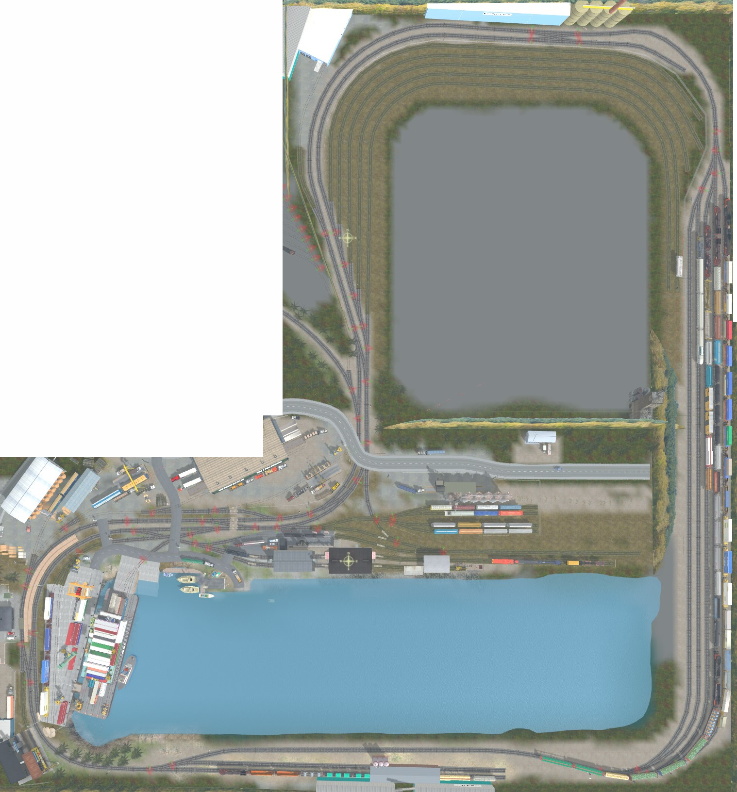
This is not exactly to plan but recreates my vision functionally and allows for experimental scenery variations. Also most buildings and roads are fully visible on the virtual layout, but are cut off at the real layout edge for the most part. Please disregard the return loop. This serves only for ease of operation on the virtual pike (as otherwise, I would have to enter its „edit mode“ to prepare for the next session).
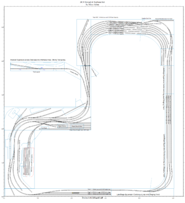
The XtrkXad version has a much more important function. It is used for printing out track arrangements true to scale and to export the same plan into JMRI. It also allows for operations on the correctly scaled plan. This is currently adapted to the plan above.

My main givens and druthers are derived from the available space, the multiple purposes of the train room and my personal preferences. I prefer switching over railfanning, so a continuous run isn’t high on my list. There is only limited room for a permanent layout, but with some clever construction, I should be able to add staging to both ends of the layout and have an operational permanent section at all times.
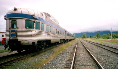
Automation will handle the passenger traffic only. One passenger train coming into the modeled area, being serviced at Stewart and returning back into staging. There is currently one problem. The train actually needs to be turned on a wye prior to leaving, as it features a single F40PH as head end power and an observation or Park Car forming the rear.
XTrkCAD enables one to export a parts list for calculating track components, lengths and costs. So here it is (based on the plan above including the small testing layout).
Well, I already mentioned it, this is a growing and ever changing endeavour. While building the benchwork, I discovered, that I had too many movable sections, on which operations depended. So I set out once again to remove the yard from the center to the main Layout.
The newer trackplan will still have a swing up section at that position, but the trackage there wouldn’t be strictly essential for most operating scenarios. It basically holds the wye and the grain facility which I hope to relocate eventually, but probably not in the next iteration of the new plan.
So what benefits does this new plan have? Well first and formost, it has a continous loop (option). This is something I really didn’t plan to do, because the room was originally meant to be used as a guest bedroom. This meant I had a convertible Sofa and a double bed inside that room. My wife sugested to throw the sofa out and out it went. And now my wife again sugested to also get rid of the bed, which opens up a ton of new possibilities. I can now have my home office desk at the location of that double bed and still have the main yard tracks above that desk. A number of new shelfes will allow for reorganising this area of the room including the 3D-printer desk, which in turn offers the possibility for the continous loop.
So the yard is now located at the top of the image around a bend with capacity for sorting 84 cars, plus 15 cars capacity on the A/D track/siding. The yard will double as Staging between sessions as long as the continous loop isn’t in place. If used this way, I can tug away a 20 Car train including two modern 6-axle locos on the mainline and a second 15 car train including two modern road engines on the siding, which even keeps the yard clear for operation. The other end of the layout will enable me to stage a 9 cars train with a single road engine and two 7 car trains with their shortline power. This will keep the main Layout operational even without the continous loop section.
Total trackage for the final version is up to just over 84 meters, which means to plan ahead for the investment. I omitted all No. 5 threewa switches, as there are no fast tracks templates for these and replaced them with standard No. 5 Switches. Also I added a No. 5 Double Crossover. There are still two more No. 3-Way Turnouts, for which I currently have no replacement. I might use a commercial turnout or try a stub switch at both locations (one being in the engine service terminal (which I might eliminate in trackplan iteration 6.23) and one at the grain elevator. This would be a cool opportunity to test precision positioning using servos or maybe stepper motor based linear actuators. A stub switch using a stepper motor for positioning would even allow for a 4-way turnout at the grain facility. Now imagine that!
The branch line at the top right side is optional too. I basicall only build the turnout and thats it for the time beeing. The swing down section is very valuable real estate and houses as much as four left hand No.5 turnouts and two No.5 Slip Switches, which is 8 remote controlled servo turnouts in a relatively compact and mobile space. This will be a challenge, I’m sure. I hav that section layed out using extruded foam board, but I do think about using a hard plywood surface instead.
The new plan would allow for adding a fourth passenger car to the VIA Train, which is actually unrealistic for most of the year, but tourists have been rumored to roam this part of the country in summer, so that could explain the extra capacity (occasionally).
Revision 6.23 (Final?)
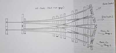
Okay, there was an issue on the foldig section for the wye and the grain facility. The northern leg of the wye had a much to shallow angle for a fold down section, so I relocated the track further out cross the gap from the side. this is still not great but an improvement. As XtrkCad doesnt allow for the construction of N-Way-Stub Switches, I laid track at that location to closely resemble the overall shape. This is not a functional XTrkCAD design, but it serves for illustration purposes here. The fold out has an unscenicked extension for the passenger train operation, if needed. It folds into the fold-down section. The Grain Elevator is a removable structure of course.

Also this central section will be one of the last stages, I plan to include on this layout. So for the time being the plan will look somewhat like this.
Handlaid Track & Scratchbuilt Turnouts
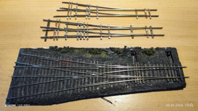
No, I don’t plan to handlay all my track. I’m going to use flextrack. But I do plan to scratchbuild all my turnouts. I’ve already done a few using Fast Tracks templates and have been quite successfull and satisfied with the results. The amount of work is not overly high. With some experience and the right tools at hand one can fabricate multiple turnouts at the same time. The more you do simultaneously build (or rather in one project), the less time you need for individual turnouts. However, mass producing turnouts isn’t as fun, as devoting your concentration and motivation to a single masterpiece. But that’s not the gist here. I want to save money, and scratchbuilding turnout saves tons of money, while resulting in much better performing and longer lasting turnouts.
Counting Double Slips and 3-Ways as two turnouts, that’s 39 scratchbuilt turnouts (of which six are done, including the 3-Way). Calculating for very little cutting losses, 75 m of Flex Track are necessary as well as roughly 40 m of track profiles. With 9 PCB ties per turnout I need to fabricate roughly 400 strips of 3mm wide and between 28 mm (normal tie) and 80 mm long (the longest tie on my 3-Way-Turnout. 3/4 of the ties on each turnout are longer than normal ties. So I’ll fabricate around 300 90 mm ties and cut these to lenght as needed, knowing, that I can make 3 normal ties out of one long strip.
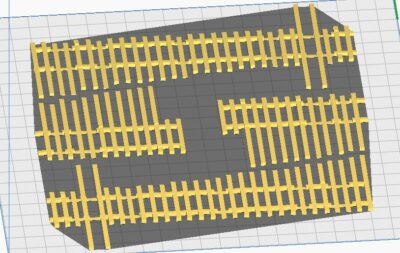
NExt to the PCB ties necessary for the flawless operation of these scratchbuild turnouts, all the ties have to be added. Thanks to 3D-Printing a tie set for two turnouts can be printed in less than 90 minutes on a recent FDM printer, like my Sovol SV05. So while building the turnouts, let your printer print the ties.
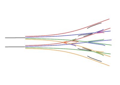
Here is a quick drawing of the proposed Stub Switch mentioned above.
Benchwork, Backdrop, Fascia and Baseboard
The benchwork will be made of 18 x 70 mm lumber supported on steel shelves, both free standing and wall mounted. Where necessary, wooden legs support the benchwork for extra stability. The benchwork forms a grid spaced no further than 40 cm apart, on which I glue the styrofoam baseboard.
As most of the modelled area will be flat, an open grid with risers and cardboard skeletal landscape grid doesn’t seem necessary. The only rising terrain will be the scenic divider between the main Layout and the East staging staging yard and perhaps some background terrain on the north west corner.
Fixtures for sensors or mechanical devices like turnout machines will get 3d-printed mounting bases glued into the styrofoam to form a rigid foundation.

The backdrop and fascia will be made of thin (3mm) high density fiberboard, which are frequently used backwalls on IKEA cabinets. I had a few of these in storage, so that’s what will be used.
Roadbed and Trackwork
The roadbed will be 4 mm cork strips (bought on a roll of 200 x 100 cm) glued directly to the styrofoam baseboard with white glue. I’m using Tillig code 83 track with wooden sleepers for the main visible track (as most prototype images along the CN Skeena sub indicate wooden sleepers).
Arguably concrete sleepers seem to be much more likely, as the rail line would have been built only recently, according to the BC Northern Story. But since it’s my railroad and this is a region with forest products being a major commercial factor, I figured my descission would be very feasible.
Ballast will be a fine grained product, more or less brown colored out of the bag. I will blend the colour to match selected prototype images.
For the classification yard, staging areas and any track covered by concrete or asphalt, I’ll use cheap code 100 track because the track profile height will not be an issue in these areas.
I plan to model my classification yard tracks overgrown with grass and moss and think, that the extra profile clearance will be the better descision in these areas. Click the link for and example photo.
The layout will be built in stages, of which all the big plans here are the „final“ stage, if there is such. A model railroad devellops, as it grows. Change is a feature that’s necessary to improve on the initial planning. So frankly, I don’t know whether the railroad will ever reach the final stage envisioned today. It might end up something completely different, but it will become something I will enjoy big time. So letz talk about the early stage of this plan. The following plan reduced the amount auf benchwork a bit and the amount of track by nearly a quarter, which also reduces the initial costs a fair bit, while maintainig the functional aspects of the plan.

I might be wrong, so I will make a small test track to check whether this works out nicely. I plan to have the yard about 5 mm lower than the main track, with about 1mm equalized by the higher track profile, which I hope will portray the impression of lighter track. Also yard tracks are usually flat on the ground without any embankment like in the following photo from WikiMedia Commons, which will also serve as the main ressource for the colour of my ballast and the amount of overgrowth between the rails/tracks on my layout.
Digital Command Control and Electrical Aspects
The layout will be controlled by NMRA compatible DCC-EX digital command control system in connection with JMRI. A dedicated Raspberry Pi will run the JMRI software.
Various microcontrollers will handle the interfacing with track sensors, turnout machines and signal masts. With track sensors being IR proximity sensors for general block occupation and staging yard automation and RFID scanners for rolling stock identification. Depending on the location on the layout wireless or wired network attached hubs will group these microcontrollers.
In order to communicate between JMRI and the various distributed micro controllers (MCUs), I’ve stumbled across MQTT, the de-facto IoT standard communication protocol, which seems to be a versatile and universal „information sharing network“ running over a TCP/IP network. Devices subscribe to a MQTT server and can create and send/publish topics and messages to the broker/server and can subscribe to/ receive Topics and Messages from the server. A topic, generally speaking, is a functional aspect of the layout, for example this could be RFID, IR-Sensor-State, Signal-Head-State, Turnout-State, Operations-Values like destination, shipper, train, load, load state, location info, etc. A message contains a payload of useful information including but not limited to the actual message, it can contain the client’s ID and also the current or next state or change of state of the respective functional aspect, like Signal-Head-Aspect, Turnout open/closed, whatever. It is effectively a command protocol on steroids. At least if I understood it sufficiently.
As of now, JMRI is capable of controlling Sensors, Reporters, Signal Heads, Turnouts, Lighting, Consisting and Throttles, as well as any custom made (or DIY) IoT scripting via MQTT, which includes using the info of the above objects for other purposes, like publishing Reporter data to a web page (i.e. to create a train manifest or switch list) in conjunction with websockets, a LAMP webserver and some code (which I am totally not capable of, but willing to learn).
To fulfill the electrical requirements of all the electronics and MCUs, there will be a common powerline or bus under the layout with feeder wires to every track section. Turnout frogs will be powered on all handlaid turnouts.
I plan to have (at least) three separate power buses under the layout to supply different electrical components. 3.3V and 5V for ESP32 and Arduino components respectively, 14-16V (15V) track power. And maybe a 7.5V auxiliary power bus to supply Arduino MCU development boards. All of these will have buck converters with a voltage display to ease their management and a separate power supply. The main power supply (PSU) will also have a rectified and adjustable power output shown on its display.
Using the power buses above, there will be the RFID-MQTT-„network“ with 3 readers concentrated on each ESP-32 board, which then connect to JMRI via WiFi (each „concentrator“ utilizing its own IPv4-address, MQTT device ID and Reader ID). Multiple reporters per connection are supported by JMRI, so that’s already accounted for. The code for this can be found at MR-RFID-ESP32 on GitHub: https://github.com/jerryg2003/MRR-RFID-ESP32.
There will be tablet-displays on the fascia (an old Huawei MediaTab 10 and an old Samsung Galaxy Note 10 2014 Edition), above the layout (an old 19in Flatscreen TV), mobile phones (as wireless throttles) and even tiny platform displays at the station will show various operational aspects during the session.
The platform signs will announce the passenger train, show its arrival time, departure time and real world destination. A similar display at the barge will show its next scheduled tour, as well as its next destinations. Simpler and larger displays or a dedicated web-page based JMRI panel will show the yard track occupation and car numbers next to the occupation of various industry tracks as well as the current operation there (loading woodchips, unloading grain, transloading mining supplies, transloading containers, etc.) and how long it is planned to take in regard to layout time. The layout time (fast clock) will also be displayed at convenient locations. Finally layout lighting will also be controlled by the fast clock (a long daytime (4 hours), followed by a much shorter night time (15-30 minutes)). Alternatively the day and night cycle can be overridden via either a web-based interfache (accessible via any browser) or an appropriate control panel. In case of any failure (causing DCC power-off), it may even be switched to maximum visiblity. It seems I can control these aspects using MQTT, which simplifies extending functionality after implementation.
List of Industry Spots (needs update)
The following locations will be handled by the operation component of JMRI (OperationsPro). Changes will occur as operational aspects dictate, that might be found during construction and operation at any later time.
- Northern Staging Yard. This three to five track staging yard represents the Rest of the world. Mainly these are other locations on the BC Northern network, of which Meziadin Jct. would be the next destination, where trains are split up going north to Dease Lake, South to Kitimat – where a CN interchange is located – or into the Nass River Sub. All in all, cars from Stewart generally are first routed to Meziadin Jct. and processed there, to be devided onto long distance trains. There are through freights to Kitimat though. The exact schedules have yet to be determined. I doubt, that more than two trains per session will emerge from staging, or disappear into staging. Having a total of three tracks available should suffice. There might be room to squeeze in a fourth track while sacrificing some train length on one of the outer tracks. Note that northern staging is one of two locations, depending on my layout construction progress.
- Stewart Timber Co. Woodchip Loader and Storage Shed – This track accepts at least one and up to four empty woodchip cars per day and ships out the same number of loaded woodchip cars, there is storage for approximately 25 carloads. The Industry needs to be switched again if more than 2 cars are processed.
- Stewart Timber Co. Loading Spot 1 (Lumber Warehouse) – This spot accepts Box Cars, Bulkhead Flatcars or Centerbeam Flatcars. Incoming Loaded cars unload plasterboard, foam insulation board and other construction materials not produced on site and outgoing cars are loaded with dimensional lumber and related forest products. Up to two incoming carloads and an equal number of outgoing carloads are possible. However the required car types might change, so an incoming car might go in loaded and out empty or vice versa, while most cars get in loaded and out loaded again.
- Stewart Timber Co. Loading Spot 2 (Loading Ramp and Gantry Crane) – This spot accepts Flat Cars, Gondolas, Bulkhead Flatcars or Centerbeam Flatcars. Incoming Loaded cars unload plasterboard, railroad ties, prefab construction materials and machinery, as well as foam insulation board and other construction materials not produced on site and outgoing cars are loaded with dimensional lumber and related forest products. As with Loading Spot 1, cartypes for incoming and outgoing cars might change.
- Stewart Station Depot. The passenger depot handles 3-6 trains per week. Monday to Saturday in summer (Apr-Sept) and every other day in winter (Oct-Mar: Monday, Tuesday and Friday). The train usually arrives on platform one at around noon and departs after about two hours from the same platform. In winter the train arrives on platform one in the afternoon, stays at one of the storage tracks for one and a half day at Western Staging Yard and departs from platform two at around 8 o’clock on the second day.
- BC Northern Express Warehouse (Spot 1 & 2: Break Bulk) – This spot accepts box cars, gondolas or flatcars (any) as loaded (70-80%) and empty cars (20-30%). It sends out loaded (20-30%) or empty (70-80%) cars too. This is a Supply base for many camps in the area, which gets supplies by train and ships to camps by truck. Approximately 5-6 Cars are handled per day.
- BC Northern Express Warehouse (Spot 3: Cold Storage), Spot 4 (outside): Break Bulk (ground level) – Spot 3 accepts only insulated box cars or reefers loaded (75%) and empty (25%) and send out vice versa. Spot 3 accepts any car servable on a team track including hoppers, covered hoppers and even tank cars. The nearby Team trank hold mobile unloading equipment at hand for this purpose. Loads and empties. Approximately 4 Cars are handled per day. Spot 4 is about to be sacrificed due to space constraints.
- Stewart Team Track (Spot 1: Break Bulk, ground level, Spot 2 (Loading Ramp and Gantry Crane): Break Bulk, Vehicles, Machinery – Box, Flat, Hopper, Gondolas, etc. Loads and empties. This location is situated on the property of BCN Express, but available for local businesses as well. Usually not more than one or two cars are processed per day.
- Northern Wheat Grain Elevator (1 loader, 2 unloaded, 2 storage tracks capacity 10-12 cars total) – this track accepts loaded grain cars and sends out empties. Rarely a bakery and wheat mill in Prince Rupert orders a carload of grain, which is then shipped by barge to Prince Rupert or routed via BCN and Kitimat CN interchange to Prince Rupert, whichever is more effective at any given time. A GP9 switcher usually handles the loading at this industry, optionally a small switcher, Trackmobile or even a wheel loader with a special coupler attachment could handle its work. About 8-12 Cars are handled per day. The track arrangement allows for one string of cars out of the two storage tracks being processed in one move and then pushed back onto the storage track. Sometime after the local switching is done the BCN power will pick up the processed cars for classification. This gains some complexity due to the yard revision. Instead of two long tracks, I’ll opt for more shorter tracks.
- BC Northern Marine Rail Barge Terminal (2 track slip, 5 track capacity (3-4 cars each) – this is in essence an interchange track that accepts any car. The barge capacity is about 20 cars, which is also the max. amount of cars coming off the barge on its arrival day and going onto the barge on its departure day. The barge is usually switched with road engines or local switchers. After processing two barge tracks the barge needs to be re-moored. The usual pattern is pulling the two outermost or seaside tracks first, then the two innermost or dockside tracks and finally the remaining centre track. Loading happenes in the opposite pattern. Theoretically railcars can be held underneath the container racks, but for safety reasons this is not allowed. With the railcars off the barge, the container load can be processed by means of two heavy lift trucks and a reach stacker (I presented the models earlier).
- Stewart World Port Intermodal Track (capacity is one 5-unit articulated doubls stack 53ft well car or 5 individual husky stack well cars), track doubles as barge switching track. Incoming and outgoing intermodal cars (Well Cars, TOFC/COFC, etc.). Depending on the barges loadout, this track might be switched more than once per session. Which the barge being capable of handling 64 (sixtyfour) 40-53ft Containers or 40-56ft flat racks above the center of the track (16 per layer, 4 layers high) and another 30 TEU (5 long and three high) evenly distributed on both sides, as much as eight 5 unit well cars or 40 individual railcars might be necessary ton unload the barge and as many again to load the barge. These will usually be distributed over the two full days the barge is in port with rail cars already unloaded and prior to loading the cars for the departing trip.
- GEM Plastics Plant (capacity 2 rail cars, Spot 1 Bulk Powder/Pellets unloading, Spot 2 Break Bulk loading) – incoming loaded Pellet Hoppers, tank cars and outgoing loaded Box Cars
- BC Northern Rail Stewart Engine Maintenance (2 tracks service 2 locos each and store an additional 2 locos each)
- BC Northern Rail Classification Yard (revised to 6 tracks, extendable to up to 2 metres each, 8 cars per track. There is a runaround on track one (the uppermost yard track, so the engines switching the barge can escape to the other end of the train. This runaround also forms part of the wye, which is used by the Bear River Explorer passenger train.
- Stewart Bulk Terminals Track 1: This industry accept open and covered hoppers and transloads mainly minerals to seagoing ships. It is part of the Western Staging Yard and processes about six cars per day. Loads in, empties out. Track capacity is 8-10 cars approxinately.
- Stewart Bulk Terminals Track 2 This industry accept open and covered hoppers and transloads mainly minerals to seagoing ships. It is part of the Western Staging Yard and processes about six cars per day. Loads in, empties out. Track capacity is 8-10 cars approxinately.
- Western Staging Yard (represents two car storage tracks of 8-10 cars capacity. It MIGHT represent a Spur into Hyder, Alaska and beyond to the Premier Mine in the future, but for now it’s just a storage track.
There will likely be changes to these locations as the layout progresses, but this quite substancial amount of operations represents the current maximum, which I can envision.
Operational Aspects, Concepts and Automation
Stewart is a stub ended Terminal. Westbound trains terminate at Stewart and return eastbound in the direction they came from. More traffic leaves Stewart north-west bound by barge. This is handled as a large industry or interchange.
There is one bulk terminal at Stewart, that is located further west of the modeled area, which is operated as an interchange staging track (loaded covered and open hoppers in, empties out).
Operations will be supported by JMRI, which builds trains and switch lists for all industries and interchange or staging tracks. Ideally the same cars going off the modelled area will return in later sessions with minimal train rebuilding between sessions. However this last aspect isn’t imperative. The main purpose is for JMRI operations to set up one single session start to end at each time.
To help turning trains in between sessions, a wye would be necessary, which also serves an important operational purpose. There is only one location a wye can be installed, possibly only temporarily. That would be from the runaround at the grain elevator towards the mainline in the top center of the modeled area. It’s not shown on the earlier track plans, as I consider the passenger automation an optional future expansion for the layout. A wye at that location would require me to place the grain bins to the right side of the unloader, which would conveniently hide a cabinet at that location. More custom track laying would also be required, which is okay.
Blocks, Paths, Sections and Signal Masts
JMRI via DCC-EX will be used for most aspects of the layout. This opens up a lot of opossibilities and a lot of complexity. So organising its setup up front seems to be a good idea. So in preparation to tha lets identify those blocks, paths and section on the layout and determine their significance in relation to JMRI. According to JMRI: Sections Documentation a section is a group of one or more connected blocks. It needs to contain one block and can either exist by itself or is connected to a block before or after it. Blocks do not need to be part of a section. There is no need for sections on the layout as there is not need for blocks on the layout unless I want to establish functionality that requires either.
Lets assume we divide the layout in to blocks which are paired into sections. Why? Because sections, unlike blocks, can have directional occupancy detection by utilizing two IR sensors (for example). By having two blocks with one IR sensor each in each section, we also have two sequentially useable IR sensors, which can utilize the directional monitoring of trains. Sections can also overlap. So if you have a siding their turnouts cvan be part of the siding section and of the mainline section. Depending on their function and location, turnouts might be defined as individual blocks. In practise the track leading to the turnout will probably also be part of that block, but that’s a flexible descision to make.
The process will basically follow this order:
- Determine all blocks on the layouts (is there a necessity to make them electrically isolated)?
- Determine all possible paths throug each block and create a list of blocks for that path?
- Determine which paths and connected blocks should be part of a section (the warehouse spur on my layout has three spots, which are effectively three blocks. with different paths to each (the spots further in to the industry include the blocks of the spots further out), but would likely al be in one section.
- Determine whether further sections are needed for RFID detection.
- Make a easily readable map representing all blocks, paths and sections.
Proximity sensors and an RFID scanners will trigger and support the automation process to handle the passenger train. This includes running the train from staging onto the layout, stopping the train at the station, waiting for passengers to disembark. Optionally uncoupling the engine for a short visit at the maintenance facility, for resanding and refueling, then back to the cars left at the platform to re-couple. To prepare for departure would involve running the train over the wye to turn it around and placing it back at the platform for passengers to mount the train for the return trip into staging, as well as running the train back into staging to stop it there for the remainder of the session. Of course this could be handled by a crew at any time by choice. Preparation for the next session would involve turning the Passenger train again. Other trains in staging would need manual rebuilding, during which the locomotives have to be put on to the other end of the train at least.
Structures and Buildings
Next to the industries mentioned above, I always wanted a few special buildings on my model railroad. Not all will fit, but I’ll try to add a few, like the Tidewater Wharf and Waterfront dioramas from Builders in Scale, or my own Lighthouse. In addition to that I wanted to have a local voluntary fire department and a Woodchip Truck unloader. I will go deeper into these aspects at a later time. THere is one thing however, that I will not be able to do on this layout: include the HO-scale Tidewater Wharf reapir dock and waterfront. This simply won’t fit anywhere.