


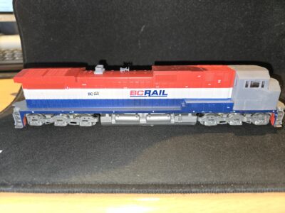
Recently I aquired an older Athearn Blue Box model of a BC-Rail C44-9W locomotive (BCOL 4641) in the iconic Red-White-Blue paint scheme. Well, turns out all BC-Rail Dash-9 units with this paint scheme were actually C44-9WL, which have a different cab and all BC-Rail Dash-9s with the Cab of that model, had the Blue and Silver paint scheme. Either way, I would have to either repaint the loco or replace the cab.
There seem to be very few videos of that particular engine in the original livery. This low quality clip was the only one I could find.
As she was one of only four BC Rail ordered that way, her sister 4644 needs to serve as a stand-in in the YouTube videos referenced in this article.
BCOL 4644 seems to be the last of the four BC-Rail C44-9WLs retaining the original livery in August 2023. Also the preview of the video above shows an interesting feature. Both, the ditch lights and the rock lights are lit and the ones on right side „look“ straight into the camera. A feature unique with Canadian units to improve visibility around curves yo spot obstacles in the dark. The rock lights are beneath the anticlimber and have a wider beam to improve visibility directly ahead of the locomotive, while the ditch lights sit above the anticlimber and have a narrower longer distance beam. This cross-eyed appearance is typical and I plan to model it. By the way, US or Canadian „international“ (cross border) units have similar lights called auxiliary lights – which have become mandatory – that are regulated to have a beam-focus parallel to the head lights.
On YouTube I couldn’t find any good quality videos of my 4641 in original livery. So here’s 4644 after its snow crash, but still in the original livery.
As a „major“ touch up is already on the horizon, I decided to go „all in“ and purchased a new DecoderWerk 70901 LokComander with SUSI connector and an additional Decoderwerk 70101 SUSI-SoundComander Module incl. matching speaker to soup up the model. The speaker doesn’t seem ideal, but DecoderWerk only offers support, if their original speakers are used. I opted for the largest one available, which just barely fits into the shell beneath the wide radiator section facing downwards (after some trimming on one side).
Here’s a photo of the situation:

As soon as everything works fine, I will probably go for a more beefy sound with a 3d printed enclosure. Perhaps I can even just modify this area to form a resonance chamber atop the speaker. It fills the gaps quite nicely out of the box, so only minor work would be necessary for that, the only caveat being my intention to make the changes reversible, if the sound shouldn’t meet my expectations.
I heard good things about iPhone 4 speakers, which come at a bargain, so I ordered a bunch, just to see how they’ll do. I’ll have to see and I’ll keep this page updated.
Update June 2024: Preliminary decoder testing.
Decoder Functions
With the eight function channels and more through the SUSI connector, I will be able to add a lot of lighting options, which will require space inside the shell and a good cable management.
However the decoder I chose came bareback. no connector wires, no plug. No problem, or is it? Well, the sound module comes with a cable. I talked with the manufacturer, regarding the feasibility of soldering a socket onto the decoder to be able to un-plug the sound decoder for any future changes (i.e. loading other sound samples). As the manufacturer states, the pin spacing of the matching connector didn’t match the decoder pinout.
So I came to the conclusion to add yet another short cable to connect the plug with the decoder pins. For ease of installation, I ordered a bunch of 4-pin 1.0 mm SH cables, with plugs and socket pre-wired. And it turns out the color coding of the cables doesn’t match the sound module’s cable. The following image illustrates how the sound module is supposed to be connected with the decoder (top) and how I plan to realize this (showing the color mismatch and the correct connection of each wire from the socket.

So, with this clarified, I identified the possible installation zones inside the locomotive shell.
Installation Zones for Electronics
1. Inside Cab in front of light bracket: 8 x 32 x 8 mm. This area seems great to store the cables and resistors for the LED Frame Lights, Ditch Lights, Front Lights and Marker Lights. Maybe it would be a good idea to have another (larger) JST-Plug there, to be able to separate the shell from the frame for maintenance. The 4 wire susi connector should offer some flexibility here. Example:
Cable 1: Common Positive (blue), (1 white) headlight, (2 green) front ditch light, (3 violet) front marker light (or other)
Cable 2: (4) frame/ stair/ number board light, (5) cab light, (6 yellow) rear head light, (7) rear marker lights
Well that’s,a lot of LEDs. I might change my mind along the way.
2. Inside Cab behind light bracket: 25 x 32 x 8 mm. This area is reserved for an illuminated cab interior. The illumination part is not decided yet.

3. Behind Cab in front of motor above flywheel: 55 x 17 x 10 mm. This location seems to be predestined to house the main mobile decoder. It could also hide all those resistors necessary for the LED lighting.
4 Above motor: 37 x 17 x 5 mm, this tiny space is still sufficient for the 70901 Decoder, as can be seen in the next photo.

5. Behind motor above flywheel: 42 x 17 x 10 mm. A space for the separate sound decoder. I will retrain the SUSI-Plug to be able to disconnect the body mounted sound module from the chassis mounted decoder. The actual SUSI plug is tiny. so I won’t run out of space.
The mounting tray shown above will get vent openings and cable routing prior to finalisation. It already press fits onto the upper motor contact spring.

6a. Under flared radiator narrow area: 42 x 18 x 12 mm. Two similar locations for one purpose. This area shall house the Speaker / iPhone speaker. This is the space used by the large Decoderwerk speaker. See next photo. If I seal this space, I might have a good resonance chamber.
6b. Under flared radiator wide area alternative: 30 x 23 x 11 mm. These are alternate dimensions for the location above. I sort of maximized the usability of this area in the image above.

Thankfully fellow Model Railroader Scott Rails has a YouTube Video detailing the installation of a decoder into that locomotive:
https://www.youtube.com/watch?v=-HhVl7AaokM
And Larry, „The DCC Guy“ made a video regarding LEDs in his locos: https://www.youtube.com/watch?v=6gNsH5hJt-A
In this video I also found the small SMD resistor breakout boards, I used in the next photo to make a resistor bank for my loco
Each „bank“ consists of two double breakout boards or adaptor boards, as they seem to be called equipped with a total of three size 1206 SMD resistors (the value depending on what you plan to do). A single LED should probably be driven at 1000 Ohm for 12 V, while two LEDs in series requite only up to 680 Ohm resistor. Note that a higher value resistor will decrease the brightness of the LED, but significantly improve its lifetime. I added a blob of solder to each of the teminal connector holes at each end and plan to solder the wires dirctly to the board. Each adapter is 14x8mm, so each bank in the photo below is 16x14mm in a nice and easy to handle form factor, as compared to three standard resistors (which are about 12x3mm each, plus wire ends). I attached double side foam tabe to the underside, to secure these inside the locomotive shell.

Sorry for the tissue residue at the bottom of the PCB on the right side, a left over from the cleaning process
Detail Parts
The model was missing a few details, so I needed to model these to complete the model. There was no horn and no exhaust stack in the box. The following photo shows the new cab (a modified model from SirSwitchalot on TinkerCAD), K3 horn, and exhaust stack. I accidentally ordered the sound decoder with a K5 horn but found out later that the engines actually had K5LA horns. Great.
Unfortunately, the cab had some strange angles and seems to have deformed during printing. Whether this was a result of the rip-off force of the rising build plate or a shrinking related issue is unknown to me. Eventually, I will have to print a new cab.
So, handpainting and aging… This doesn’t go well together. Many years ago, I was able to draw sharp and straight with a brush. These times are over. The front stripes should have been straight and sharp, and if I can see the discrepancies, so can others. The question is: Good or not good enough? I will have to make decals anyway, so a couple of additional stripes shouldn’t be a problem.
Also, this paint scheme seems to be very hobby friendly, as we can easily produce coloured decals for white backgrounds, but no white stripes or text on a home printer.
However, by ramping up the amount of detail, I will need a better cab. There needs to be an opening and LED holder for the step lights, head lights, and class lights, including wire routing. The same is necessary for the number board inserts, which also needs a light routing block, which I plan to print in transparent PETG. I guess the diffuse nature of the printed PETG won’t be visible on the number boards.
The tiny step light will be an interesting modelling feat. Thinking about it this very moment, I think I could utilize another transparent light routing block to rout some light from the head lights to this part. A separate LED would be better still.

Lighting & Super-Detailing
With this model I plan to realize a few lighting options, like running lights/underframe lights, stair lights, cab & number board lights, class lights, rock lights and the like, if applicable.
More detail work could be done. The original engine only has a single rear headlight and no rear ditch lights, which indicates, that it is not destined to operate backwards (long hood forward) at all on the mainline. This is common on canadian engines.
The model only has Athearns generic 3 chime horn, while the prototype had a five chime horn with all flutes facing forward on a elevated mount or riser.
There are no grab irons or hanrails on my model (yet). I will add them in the near future.
There was no snow plow included with the model, no brake wheel, no MU hoses or uncoupling levers in the box. This will also be fixed.
Reference Models and Reviews
The most recent adaption of this prototype comes from Athearn in its current Genesys series, where it received good praise and rankings.
The vvideo above goes thoroughly through all features and answere quite a few questions regarding the go-to detail for my old blue box model.