
When I started to think about using RFID tags and readers to identify my rolling stock for various purposes, I searched the net high and low for easy to understand layman’s setup information. Basically I wanted to interface my RFID readers with JMRI.
Suggested reading to get primed on the idea: http://www.pcrnmra.org/pcr/clinics/RFID-in-Model-Railroading-20130123.pdf
RFID for Model Railroads RFID4MRR-Gruppe (groups.io)
The most promising find so far: https://github.com/jwkelly49/SerialRFID
The JMRI page on that topic is very abstract and I wasn’t able to get any ID into JMRI. So my plan is to tackle that problem during the next weeks and write about my research here.
The primary goal will be providing a step to step guide to integrate cheap RFID RC522 Boards via (daisychained) Arduino(-s) into JMRI in such way, that JMRI’s inbuilt functionality can be used to route cars on any layout.
There will be a German version if this page too.
JMRI & RFID using dirt cheap RC522 Modules
Update 06.02.2023 – Where are we today?
Good question one might say. As easily visible, I havn’t posted any updates on this, which might indicate nothing happened. Guess what, that’s exactly what happened (or rather didn’t happen). I was out of the hobby for quite some time and still haven’t found the time to get back into it. Time and time again, I shuffle through my electronics boxes and stumble over the RFID modules with the idea of tackling this matter for good. Same situation yesterday.
I thought maybe to compile a list of Information regarding this topic and related aspects below, to have the intermittend research results at hand when going over my stuff next time. So lets Start on JMRI’s ressource page and the go from there.
This page will likely remain an English ressource, until I found a definite approach.
Project for 2023 and beyond…
From the links above, please take a closer look at the solution that apparently works well for the McKinnkley Railway. They are utilizing Eccel Technology Ltd. Products, which are distributed for example by digikey, which ist great, as they are delivering to Germany and allow small quantities.
The product I am most intrigued with is the 10 mm by 50 mm MUX Antenna with an attached 300mm or 800mm cable, as it will fit in between HO-scale tracks and thus eliminate or minimize the interference of the rails or other material between the tag reader and the tag passig over it. It is usually connected to either a standalone Pepper C1 Wi-Fi capaple RFID Module or a Pepper C1 MUX Multiplexing board (which is a Pepper C1 with a multiplexer to bundle a total of eight antennae, which can be sequentially polled).
This product got me thinking about designing my own reader or at least pcb antenna as a diy project and getting the pcb’s done through aisler.net (I have worked with them before and they’re great). However, I know just about nothing about rfid – radio design and frquencies and such, so I might end up using a readymade product after all. You’ve been warned 😉
So is this any easier to integrate with JMRI? No! It is not a Model-Railroad product, thus the designer didn’t care about any compatibility or usability for model railroad applications. It’s just a hardware solution.
So that being said, I’ll start with updating the Layout Setup to current software versions of Arduino IDE, JMRI, Java and whatnot.
JMRI Setup
On an abstract design layer I think it’s communication should work like this:
JMRI – RFID-Reporter – CMRI-Node-Definition – CMRI-USBConnection – Arduino-Microcontroller – CMRI-Nodes – RFIDReaders
Therfore my sketch should write each Tag-ID not only (serially) to display, but also (serially) to CMRI. That can’t be too hard, can it?
More Links:
JMRI Arduino Setup – https://www.motorhomesites.org.uk/railway/JMRI_Arduino_Setup.php
Hardware Support: Using Arduinos with JMRI – https://www.jmri.org/help/en/html/hardware/arduino/index.shtml#example-CMRI
Hardware support: Multi-bit and Byte Communication Using CMRI – https://www.jmri.org/help/en/html/hardware/arduino/ArduinoCMRIByteComm.shtml
CMRI Menu – https://www.jmri.org/manual/DP3_2-14_manual/Main_CMRI.shtml
Arduini · GitHub – https://github.com/Arduini-Projects
What I learned from these: CMRI is NOT the correct way to report serial data to jmri unless you find a way to process that data on the microcontroller in such a way, that only defined bits/bytes are transmitted. There is some seemingly contradictory info available, though.
You could encode each tag ID into a 8 or 16 bit address by first comparing it with a database. This requires a lot more memory (a job for an ESP32 perhaps) or some sort of tcp/ip network connection to make use of common internet.
Some of the following Info is shamelessly copied from JMRI’s documentation utilizing it’s corresponding License: https://www.jmri.org/copyright.shtml. I’ll link to the corresponding pages.
JMRI: Reporters Documentation
What is a Reporter?
A Reporter is JMRI’s way of representing information reported back from the layout.
A Reporter can contain arbitrary information, unlike a Sensor which is only ACTIVE or INACTIVE. Each Reporter is associated with some specific source of information on the layout, and makes that devices information available to the rest of JMRI.
The initial implementation is for LocoNet (Digitrax) transponding, where the Reporter provides access to information from Digitrax BDL168 cards with RX4 transponding sensors. When the BDL168 reports that a decoder has been seen in a transponding block or is not longer visible in the block, the corresponding Reporter will display messages like „1234 enter“ and „1234 exits“. There is also a LocoNet Reporter implementation for displaying messages from Lissy detectors.
How to setup Reporters
The Reporter Table
The Reporter Table provides easy access to the contents of all Reporters that JMRI knows about. There’s also an „Add…“ button for creating your own internal Reporters; JMRI automatically creates Reporter objects for devices on the layout.
Displaying Reporter Values on Panels
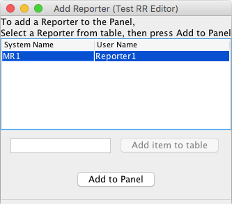
A Reporter’s value can be displayed on a Panel via an icon. To do this:
- On the Panel Editor window for your Panel, find the „Add Reporter“ button.
- In the text box next to that button, type the user name or System Name of the desired Reporter.
- Click the „Add to Panel“ button. The Reporter icon will be placed on your Panel. If it’s not visible, that might be because the value is currently blank; use the Reporter Table to change the value to something that will be visible.
- You can drag the icon to where you want it in the usual way.
- The pop-up menu on the icon will let you change the formatting.
Saving Reporters to disk
Reporters are kept in your layout configuration, along with Turnouts, Sensors, Signal Heads, control panel setup etc. To store this information on disk, allowing you to reload it next time you run JMRI, see Loading and Storing Your Work.
JMRI-Object: Interface Reporter
public interface Reporter
extends NamedBean
Represent a device that can report identification information.
Reporting devices might include:
- A DCC device that reports a locomotive number when it’s in a particular location
- A device that reports something about the layout environment, e.g. the current drawn or light intensity
- A device that reacts to some happening on the layout with a complicated report
In contrast to Sensors, a Reporter provides more detailed information. A Sensor provides a status of ACTIVE or INACTIVE, while a Reporter returns an Object. The real type of that object can be whatever a particular Reporter finds useful to report. Typical values might be a String or Int, both of which can be displayed, printed, equated, etc.
A Reporter might also not be able to report all the time. The previous value remains available, but it’s also possible to distinguish this case by using the getCurrentReport member function.
Uses of Interface jmri.Reporter
JMRI-Object: Interface ReporterManager
public interface ReporterManager
extends ProvidingManager<Reporter>, NameIncrementingManager
Locate a Reporter object representing some specific device on the layout.
Reporter objects are obtained from a ReporterManager, which in turn is generally located from the InstanceManager. A typical call sequence might be:
Reporter device = InstanceManager.getDefault(jmri.ReporterManager.class).newReporter("23",null);
Each Reporter has a two names. The „user“ name is entirely free form, and can be used for any purpose. The „system“ name is provided by the system-specific implementations, and provides a unique mapping to the layout control system (for example LocoNet or NCE) and address within that system.
Much of the book-keeping is implemented in the AbstractReporterManager class, which can form the basis for a system-specific implementation.
JMRI-Object: CollectingReporter
public interface CollectingReporter
extends Reporter
This is an extension of a reporter device that is capable of collecting multiple reports in a collection. The type of collection is not specified by the interface, since that may be determined by the application.
The Reporter Table
JMRI „Reporters“ show status information received from your layout. For example, Digitrax transponding provides information via JMRI Reporter objects. The Reporter Table shows all the existing Reporters and their most recent status information.
For more information on Reporters and their use, see the main Reporter Help page.
Hardware Support: Using Arduinos with JMRI also describes howto daisy-chain several arduinos in one RS-485 „bus“ via USB. It also states that: „
Serial communication
Arduinos can be directly connected to a USB port and use serial communications via a Jython script executed in JMRI. An example is included in the JMRI Jython directory. Geoff Bunza describes a serial communication script for collecting sensor data from an arduino. It is not necessary to configure a JMRI system connection to use direct serial communications.“
This kind of supports my earlier observation, that MCRI is probably not the way to go with reporters, but I might be surprised in the end.
The serial communication script just mentioned is probably the gateway to transport the RFID-Tag-IDs into JMRI. Lets see:
# Try to send and receive some bytes via a serial port
#
# Author: Bob Jacobsen, copyright 2009
# Part of the JMRI distribution
#
#
# We use an Automat object to create a separate thread
# that can sit there, waiting for each character to
# arrive.  Sending characters, on the other hand,
# happens immediately.
#
import jarray
import jmri
import purejavacomm
class SerialPortTest(jmri.jmrit.automat.AbstractAutomaton) :

    # ctor starts up the serial port
    def __init__(self, portname) :

        # find the port info and open the port
        print "opening ",portname
        self.portID = purejavacomm.CommPortIdentifier.getPortIdentifier(portname)
        self.port = self.portID.open("JMRI", 50)

        # set options on port
        baudrate = 9600
        self.port.setSerialPortParams(baudrate, purejavacomm.SerialPort.DATABITS_8,
                                    purejavacomm.SerialPort.STOPBITS_1, purejavacomm.SerialPort.PARITY_NONE)

        # get I/O connections for later
        self.inputStream = self.port.getInputStream()
        self.outputStream = self.port.getOutputStream()

        print "Port opened OK"
        return

    # init() is the place for your initialization
    def init(self) :
        return

    # handle() is called repeatedly until it returns false.
    #
    # Modify this to do your calculation.
    def handle(self) :

        # get next character
        next = self.inputStream.read()

        # this sample doesn't do anything with that character except echo it
        print "rcv", next

        # and continue around again
        return 1    # to continue

    def write(self, data) :
        # now send
        self.outputStream.write(data)
        return

    def flush(self) :
        self.outputStream.flush()
        return

# end of class definition
# create one of these; provide the name of the serial port
a = SerialPortTest("COM1")
# set the thread name, so easy to cancel if needed
a.setName("SerialPortTest sample script")
# start running
a.start();
# setup now complete, try to send some bytes
a.write('H')
a.write('e')
a.write('l')
a.write('l')
a.write('o')
a.write('!')
a.write(0x0D)
a.flush()
print "End of Script"
Not that I have the foggiest notion about what’s going on there. But that might change.