


I’m not the most focused model railroader left on this planet. After building most of the basic benchwork for the main layout, I realized that I needed to explore a few more things in electronics, prior to continuing. Mainly to avoid ripping off track, that’s just been laid (and boy that stuff got expensive). Track occupancy sensors, reporters and signal wiring all require some consideration, before bringing out the ballasting crew.
Now, I am aware, that there are several approaches to get where I want to arrive some day, one very feasible being: „Get your trains running quickly“. That essentially means building most of the trackwork first and worrying about drilling holes later. That’s a great approach. I might reconsider mine.
So, none the less, I am currently building a shower stall in the attic, which proves to be time consuming. Considering, I’m still working full-time, I’m trying to squeeze in some modeling-time in the rare hours between these tasks. So to see at least some progress somewhere, I have started to build the stow-away Test-Layout mentioned a few times earlier on this site. Manily to test my skills, but also to enjoy the building, modeling and landscaping part of the hobby along the way.
Operations wise it is currently a dull layout. One mainline and one single trailing industry spur. It’s not bad for an office shelf though. Short 10 minute sessions can be very appealing in this context. A small three car local going in engine first, picking up one or two cars from the spur and setting out as many cars afterwards. Then re assembling the train and off it goes either backwards to where it came from or forward to whatever imaginary location would be next on the line. With brake tests and other simulated work, it could even fill a 15 minute operating session.
So what’s the plan?
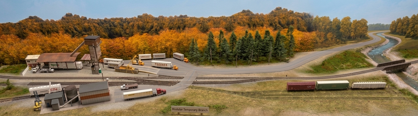
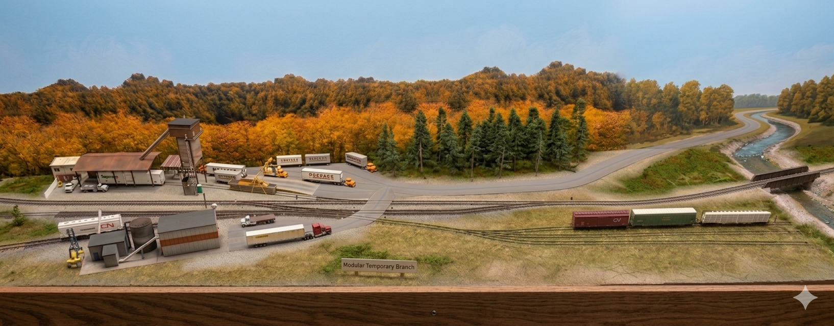
I plan to add a runaround track, a second trailing industry spur and a facing – and very overgrown – three track switching yard to the front of the layout. To allow for reasonable switching a short lead track will be added. See the image of the virtual layout below.
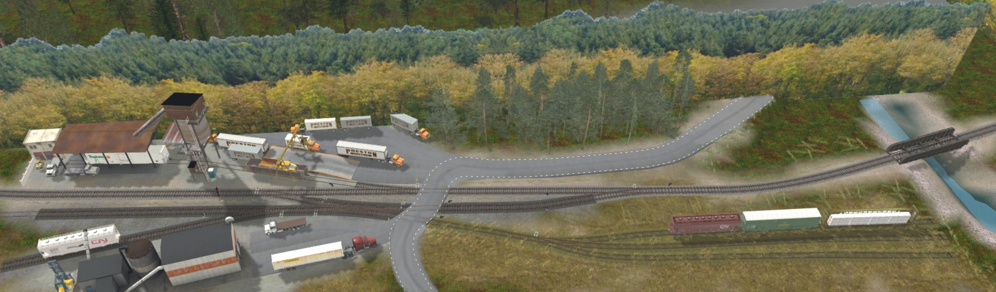
This layout measures 270 x 60 cm, adding 30 cm to the front of the existing layout, by extending the benchwork accordingly.
I started reworking the bench work, by simply screwing additional pieces of lumber to the existing frame. That however wasn’t a clever idea at all. The rigidity was terrible and I elongated the layout by about 5.6 cm and thus exceeded the height of the ceiling with that, shattering my plan to store it vertically next to the chimney, when not in use. So essentially I will have to make a new frame, but risk destroying already shaped up scenery. On the other hand, keeping the current frame will introduce unnecessary weight next to the reasons already mentioned, which will make handling the thing much more difficult.
Split Frame / Modular Layout
I’m also considering to literally cutting it in the middle, which conveniently wouldn’t have a too complex track arrangement to make that work, and gain transportability with that, by creating two 60x135cm modules. But I don’t think I’ll go this route for the moment. The whole idea was having a layout, that could be set up in minutes without assembly. Essentially just to grab the thing, place it on (foldable) legs and plug the power in.
A dedicated ESP32 based DCC-EX bWiFi Base Station is already assembled and currently attached to my windows PC based test-environment. It has all that smooth: WiFi, MQTT, JMRI-Connectivity, IR-Sensors, RFID-reporters, JMRI compatible signalling and servo based turnout motors configured, as well as a DIY dual battery handheld throttle (also ESP32 based).
It will be mounted into the frame/benchwork next to its PSU. There will be at least two MCU power busses (3,3 volts and 5,0 volts) and an adjustable track power bus (12-18 volts) under the layout.
Now that the shower stall is done…
After four and a half months, I finally declared the shower stall, that stalled the progress, finished. A small wellness oasis next to the layout room, not only for my precious wife, to be honest.
But now the summer is about to start and from experience, I’m not dedicating a lot of time for model railroading during summer. I use the time for my other hobbies (camping, reading and writing). So don’t expext any progress during the next few months, please. I’ll be back at the layout later this year.