


So … I need a boat…
Meanwhile on the layout…
This picks up where we left from the article:
JMRI Operations – Barge Operations
Frankly, I haven’t done much. The layout table mostly serves to lay out tools and modelling supplies most of the time, without much modeling going on.
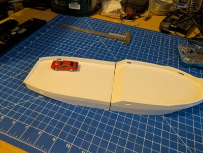
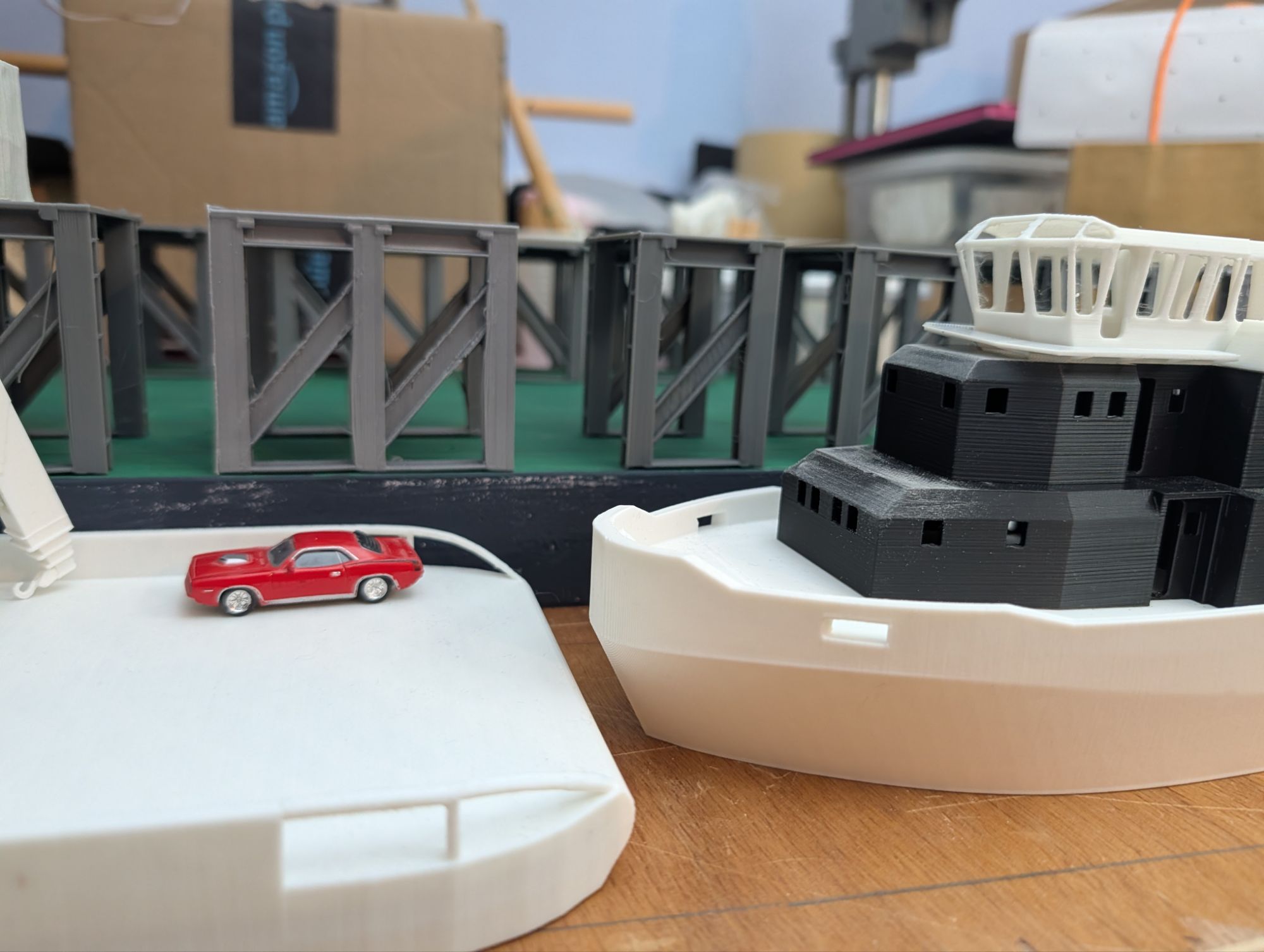
There is the barge, that hadn’t been completed and the search for a suitable offshore tug that would be able to handle the big car float.
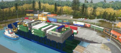
The current state of the barge or car float hasn’t changed much. The main reason I built the preliminary hull was to help with the track laying for the barge slip, to gauge space requirements, track heights and such. So this photo is a little bit older, but it captures, how the custom 3d object I put into Trains (above) translates into the actual model.

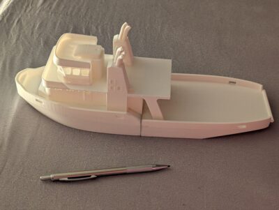
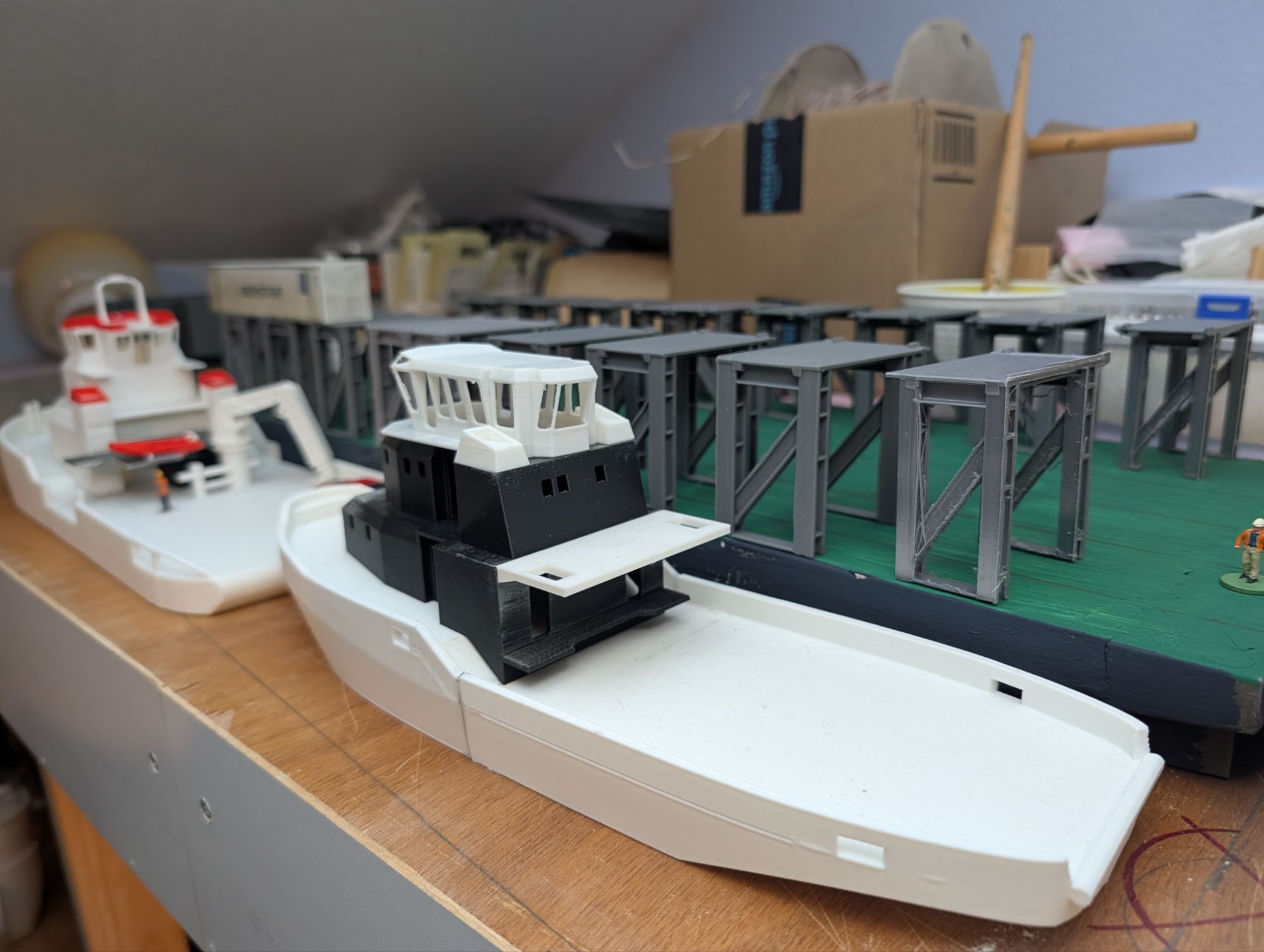
The tug hasn’t been worked on either. At least in this regard I just finished 3d printing the hull of the tug, as the following photos show.
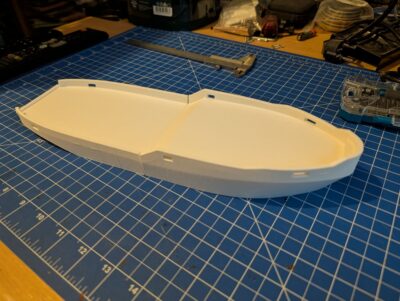

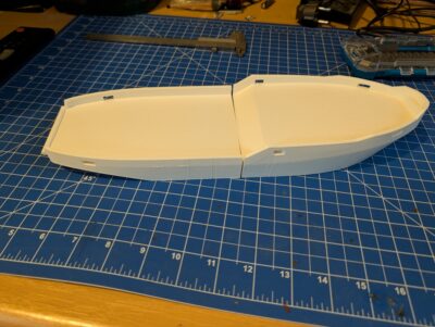
As can be seen there has been some warping on the model, which needs to be sanded away, prior to joining the two halves of the hull.
The hull is approximately 13.5 inches long and I placed an HO scale car on its deck for comparison.
The boat is intended to work as a barge tug, but should occasionally serve as a supply vessel for BC Northerns various landings and to supplement it’s fleet in regard to the (fictional) Offshore Windpark contracts.
So next to a heavy Winch and tow hook, the ship will receive a heavy duty deck crane to manage some anchor handling and deck loading. The stern thus features a collapsible cable guide as well as a (non-functional) stern roller for anchor lifting. I might consider a specialized A-frame that folds two ways to form the cable guide when towing, while working as an A-frame when extended.
I’ll provide prototype info, if that idea has seen feasibility in the real world.
https://cobiaoffshore.com/products/a-frames/
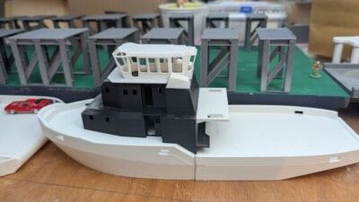
So the hull above, now with its superstructure will be (roughly) finished and used as my technological demonstrator.
Sort of.
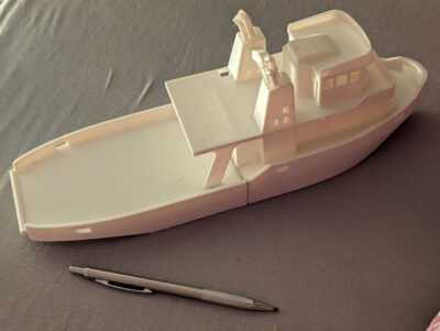
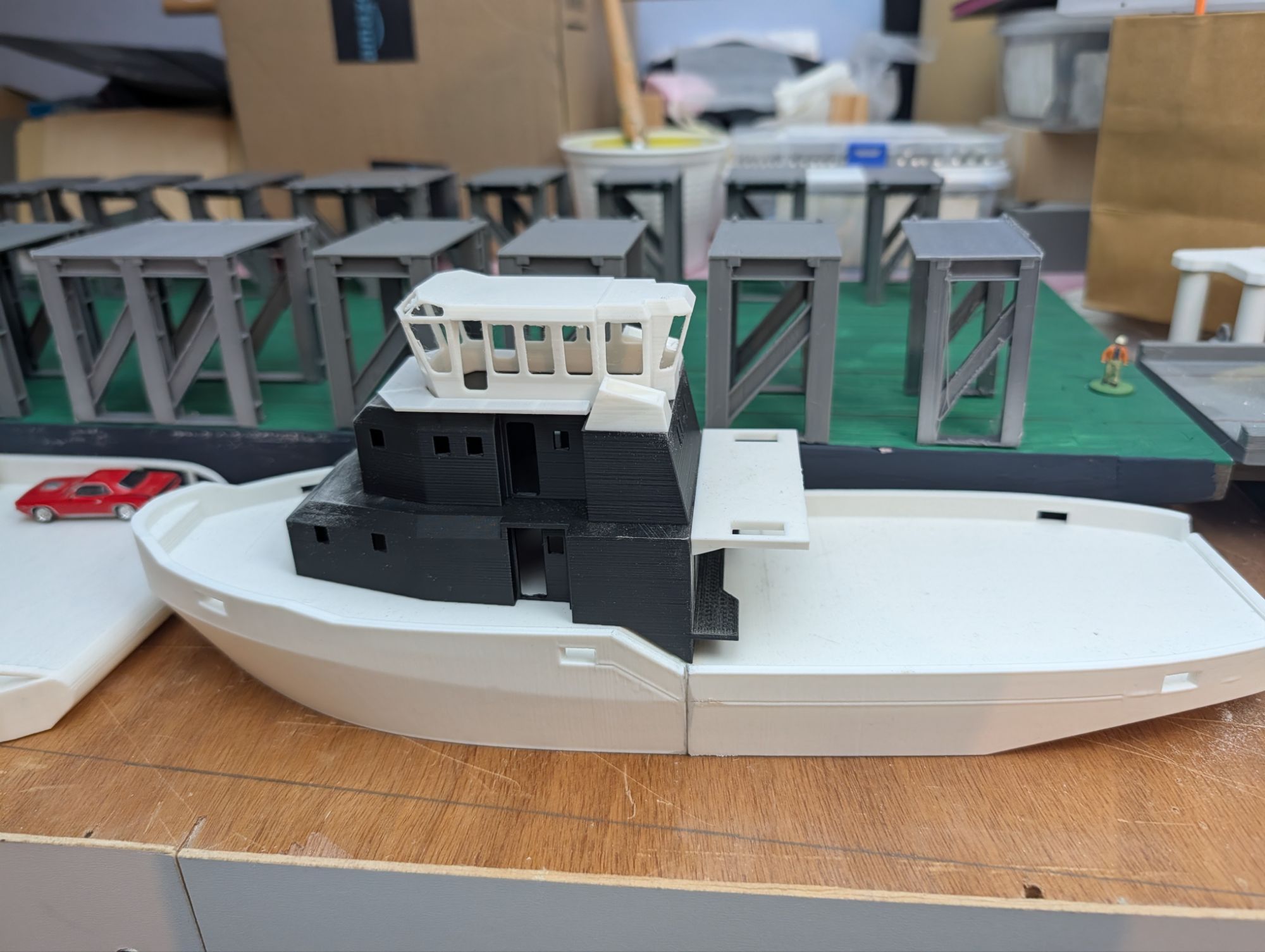
Here are some photos of the current state. The superstructure is only temporarily fitted to the hull, by the way, as some sanding and filling is still due.
I remixed the hull and the superstructure from tthe following sources:
Prepping the hull for 3D printing was a bit tedious for all the contradicting geometry after importing the Collada file (DAE format) into blender.
Then cutting the hull at the desired waterline, repairing the mesh, solidifying the mesh (and the modifier in Blender had other ideas than clean geometry after applying it (duh). In the end, I modelled the inner hull walls and deck from scratch.
After spending hours on the hull, I didn’t want to invest more time for the superstructure and went looking on the Internet
I found a cool model on Thingiverse (see link above), which only needed slight remixing:
I extended the lower edge of the main deck to work with the contour of my already 3D printed hull. Then I positioned and mirrored (or duplicated) the doors, windows and louver inserts and positioned them in their cutouts and added a self designed and modelled exhaust pipe replacement for visual variation and fun. After arranging the multiple parts into Main deck and Wheelhouse, I exported to STL, loaded them in Prusa Slicer. Repair and slice. Done.
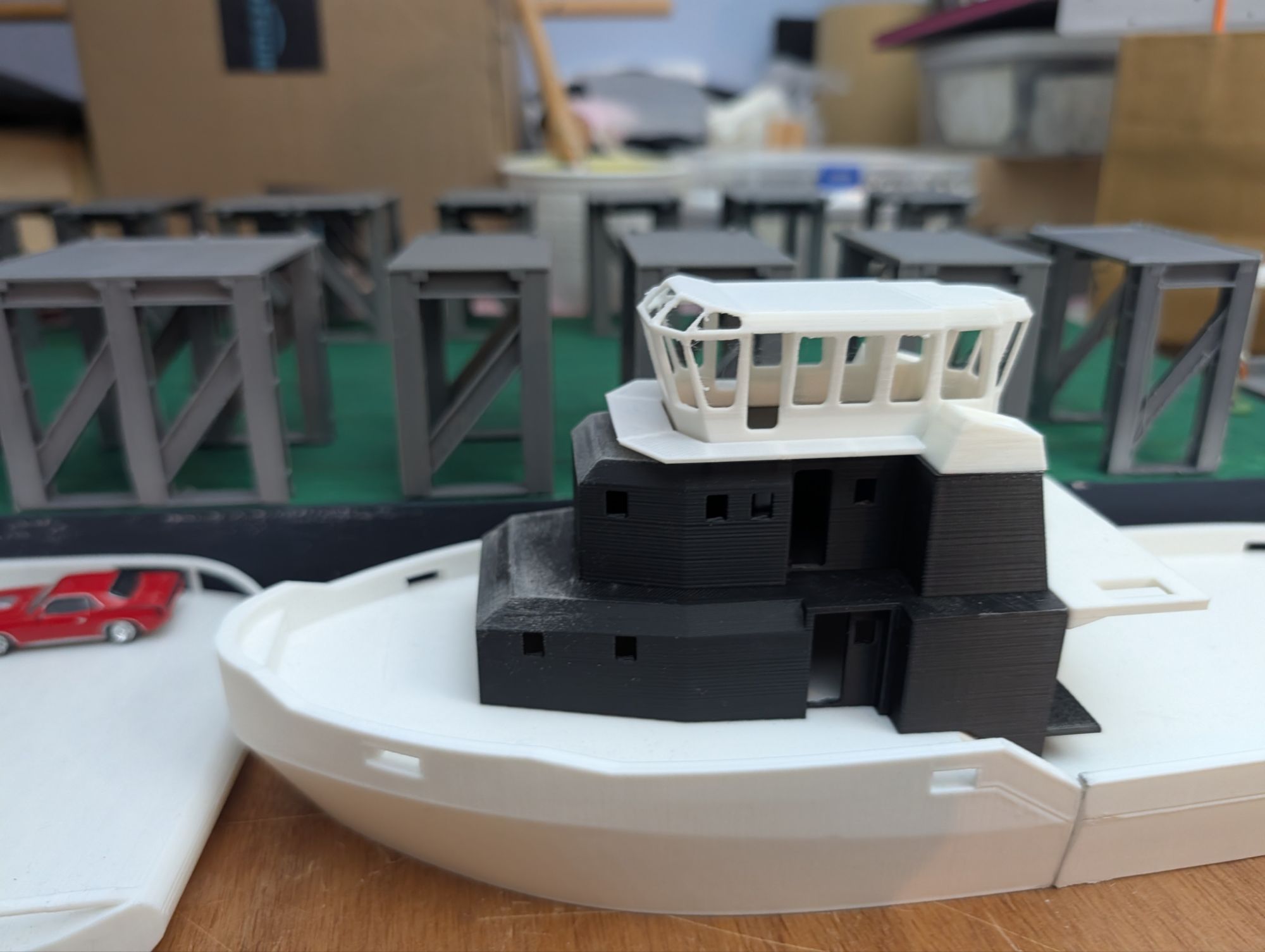
The gallery below shows the first tug model in its latest state from various angles. It has some scaling issues and it follows no particular prototype. I’m not very happy with it as the final model, but it’s a solid stand-in.


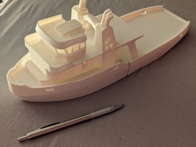

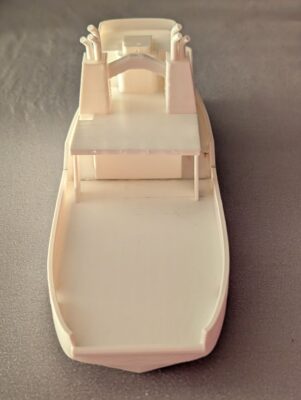


Well even though I quite like the classic look of the boat, I think it’s superstructure is too wide at the bow and about 10% too large altogether. So I thought either to reprint it scaled to the intended size or to model a new Superstructure for the boat. As reprints at scale are only a matter of doing it, as compared to the fun to create something new, I opted for the latter.

Next steps will be the funnel, doors, ladders, handrails, winch, crane and a dinghy on its davit. Let’s see how that goes…