Hardware and Wiring
I finally found a somewhat reliable solution for my RFID project. There are a lot of microcontroller options available, and it is possible to extend this solution if there are more hardware serial ports available on the arduino board.
I am not really a code juggler, so I need to keep things simple. My RFID Scanner allows two RDM6300 readers connected to a single Arduino Nano to send tagIDs via USB to your JMRI-equipped Computer.
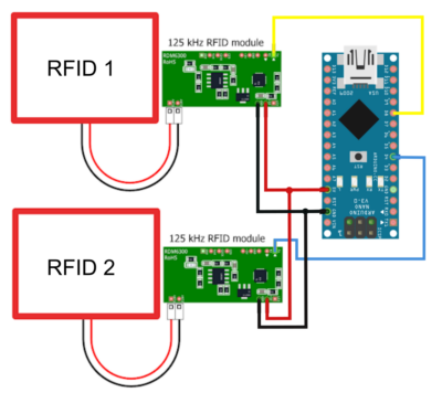
The following image shows the wiring and hardware of what I call the BCN RFID-TwinReader. For each such setup, you will have to configure the arduino sketch for the correct RFID-Reader address (this is not strictly necessary, as JMRI distinguishes the readers by port also, but it helps organizing things).R

As you can see, the wiring is simple and the cost is minimal (an Arduino Nano sells for less tahn 5 Euros, as do each of the scanner modules, which is quite affordable. Either the 125 kHz RFID module and the RFID-Antenna can be located at some distance from each other, which would allow you to cluster the modules in certain placees for easier maintenance and the wire the antennas to their respective track locations.
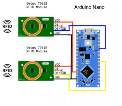
For the GWIOT 7941E Modules the wiring is nearly identical. There is GND – VCC – TXD. As these Reader often come with a 3-wire cable, I have opted to use an I/O shield for the nano and soldered Pin-Headers to the End of the cable following the GND – VCC – SIG order of a servo-cable (which provide some polarity protection this way).

RFID Tags
Please keep in mind, that tiny glas tags require more precision and reliability. I had very little success with so-called „bird“ tags with this setup and would not recommend it. This works well for 25mm ME4100 tag however, which are cheap and relatively easy to install on HO scale or large rolling stock.
Arduino Sketch
On request for the time being, as I’m still testing this mess, if your interested, please be aware, usage is non-commercial only, Provided „as is“ (no support, no guarantee, no warantee). The code is commented and should easily describe what it does. Contact me via e-Mail (see imprint) and use a descriptive referrer like „Question regarding RFID for JMRI on BC Northern Rail“ or what ever you could imagine not being recognised as spam 😉
JMRI Setup
Occasionally I will refer to my BCN RFID-Twin-Reader as RFID-Concentrator (or just concentrator), to signify the JMRI connectivity method.
The following image shows the basic settings in PanelPro
The ID within the concentrator range shown needs to be configured prior to uploading your sketch. JMRI will prefix each reader with the connection prefix, followed by an R (for reporter), a reader ID (1 or 2 in this case) and a letter from the above range (A-H). Here is the corresponding reporter table.
You can assign meaningful names to each reporter, to mark locations. Whenever something is reported over this connectionthe current an teh last report are stored in this table.
Locations are used to store cars or to move cars to and from. Each place any car can end up in, has a track legth, which determines how many cars it will hold. It shows how much track length is occupied, how many cars are in each location, whether there are any locos and how many cars are ready to be picket up and how many could be set out at each location. This information in used by OperationsPro to route cars over the layout.
This will be useful, when assignig TagID to cars from your roster, as the TagID will be automatically replaced by the user name of that tag (in this case CN 603847, which is an old 52ft Bulkhead flatcar.
Here is the TagID table showing how this is tied together.
Future expansion
* I2C to bundle all Arduino Nano concentrators for connecting on one USB port
* IRQ driven modules for even more scanners per Arduino Nano
RC522 13,5 MHz readers
I should have searched some more, because here is a very elegant solution of eight RC522 readers connected to an Arduino Mega including some code: https://groups.io/g/jmriusers/message/215219


